Final Rover Design
For this assignment we had to design a remote controlled vehicle that travels along five different tracks that had obstacles, hills, sand, and gaps to gain points. To finish all of the courses the vehicle needed to accelerate, maneuver, climb hills, decelerate quickly, and maintain traction on various surfaces. The main restraint was the type of motor we had to use, and that the motor had to be "stuck" in the on position for the entire round.
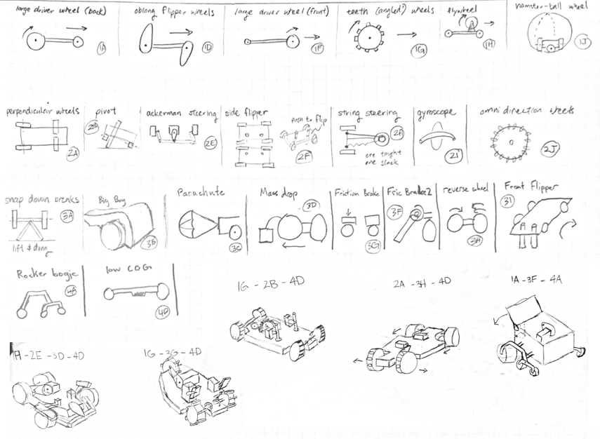
Concept Sketches
Using C-sketching, brainstorming, and other concept generation techniques our team came up with a variety of concept fragments to solve each requirement. These were then mix-and-matched to form full concepts as seen in the drawings to the left. Using engineering strategies such as winnowing, pugh charts, and weighted decision matricies we narrowed our concepts down to a final decision. We also realized during this stage that we could keep main elements, steering, acceleration, and braking as seperate modules to reduce the risk of one part negatively impacting another.
Once we had a final design in mind we needed to test out some of the components for the rover for feasibility and to see if we needed to make any changes. Our goal during prototyping was to reduce cost and make it with recycled materials that we had on hand. As you can see in the picture we used 3D printed scraps (the black bridge trusses), bubble tea straws, skewers, hot glue, and even a wooden fork. This prototype proved that an ackermann steering system, a snap down brake, and a 10:1 gear ratio to the back wheels.
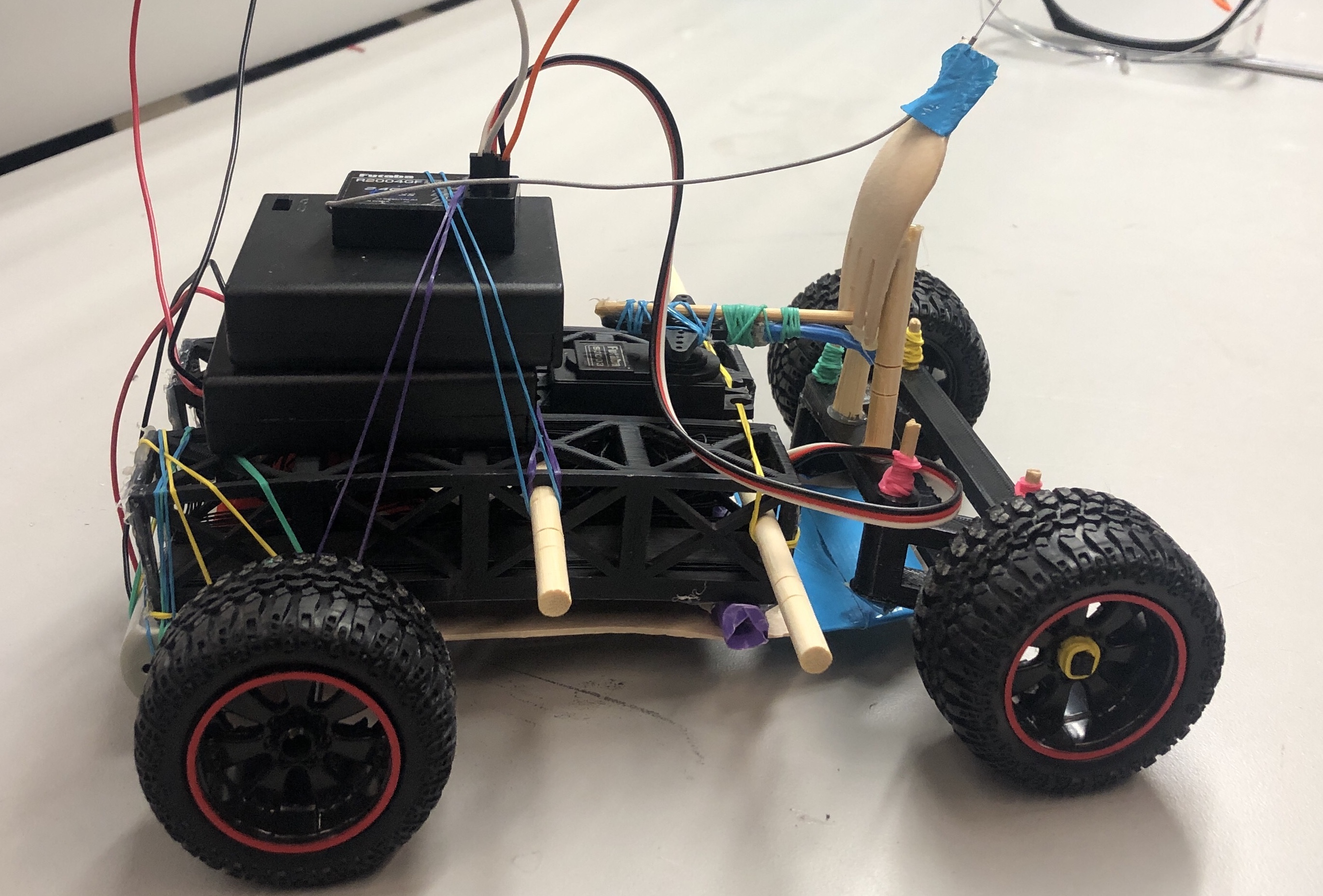
Prototype
Ackermann Steering System
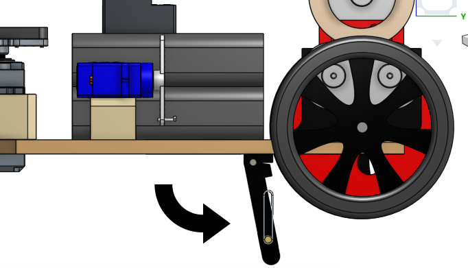
Snap Down Brakes Lift Back Drive Wheel Off the Ground
Just because you've designed something in CAD doesn't mean it will work in real life. So we continued to update the CAD alongside building the rover so we could use them both to validate each other. During testing many things broke or had to be redesigned, so keeping the CAD up to date helped us rebuild quickly. Some of our biggest challenges in building came with motor power for climbing hills, machining an accurate enough gear box to reduce friction in the driving gears, and designing a robust enough steering system that doesn't break on impact.
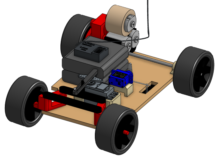
Final CAD
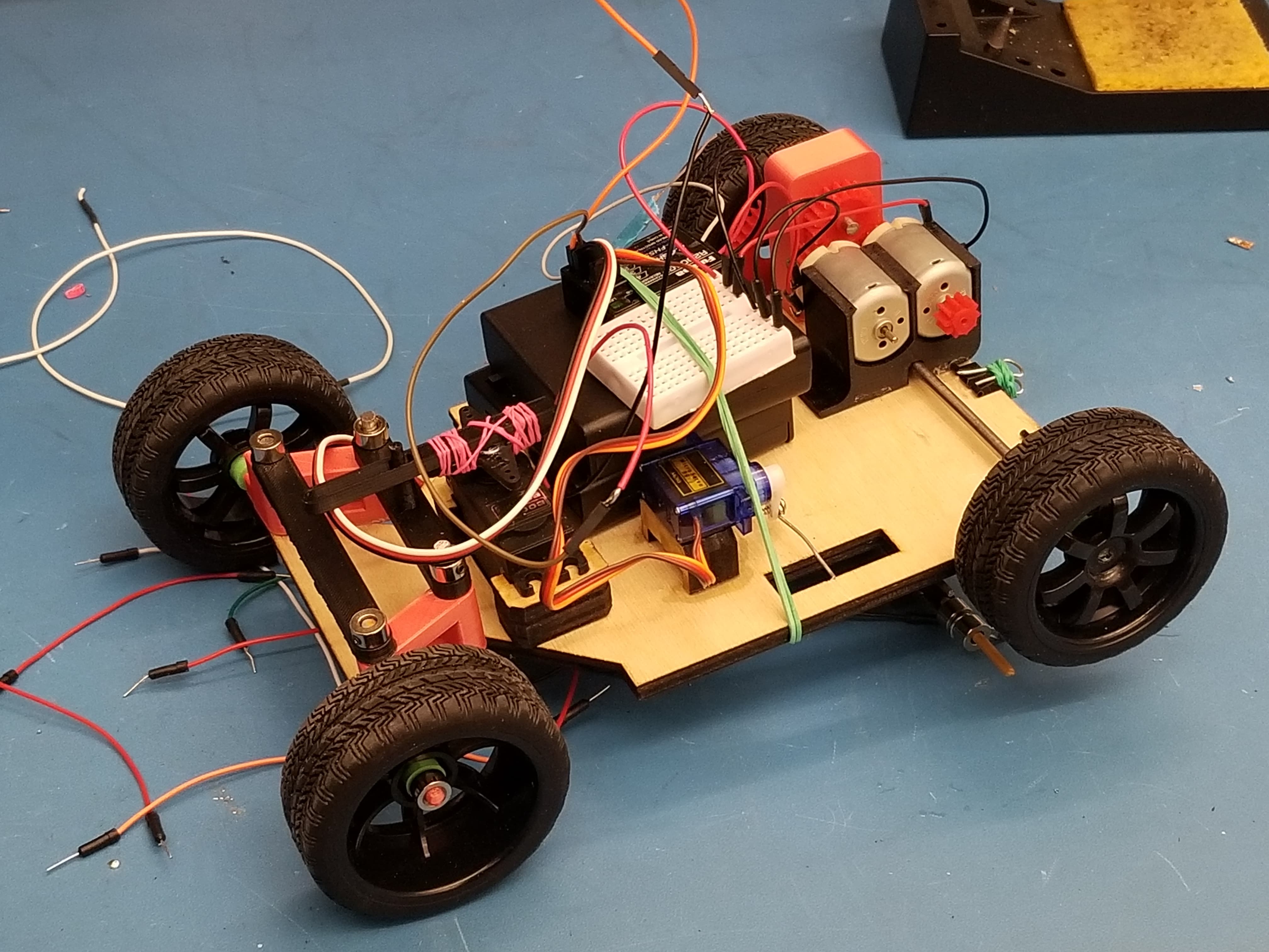
Final Built Rover
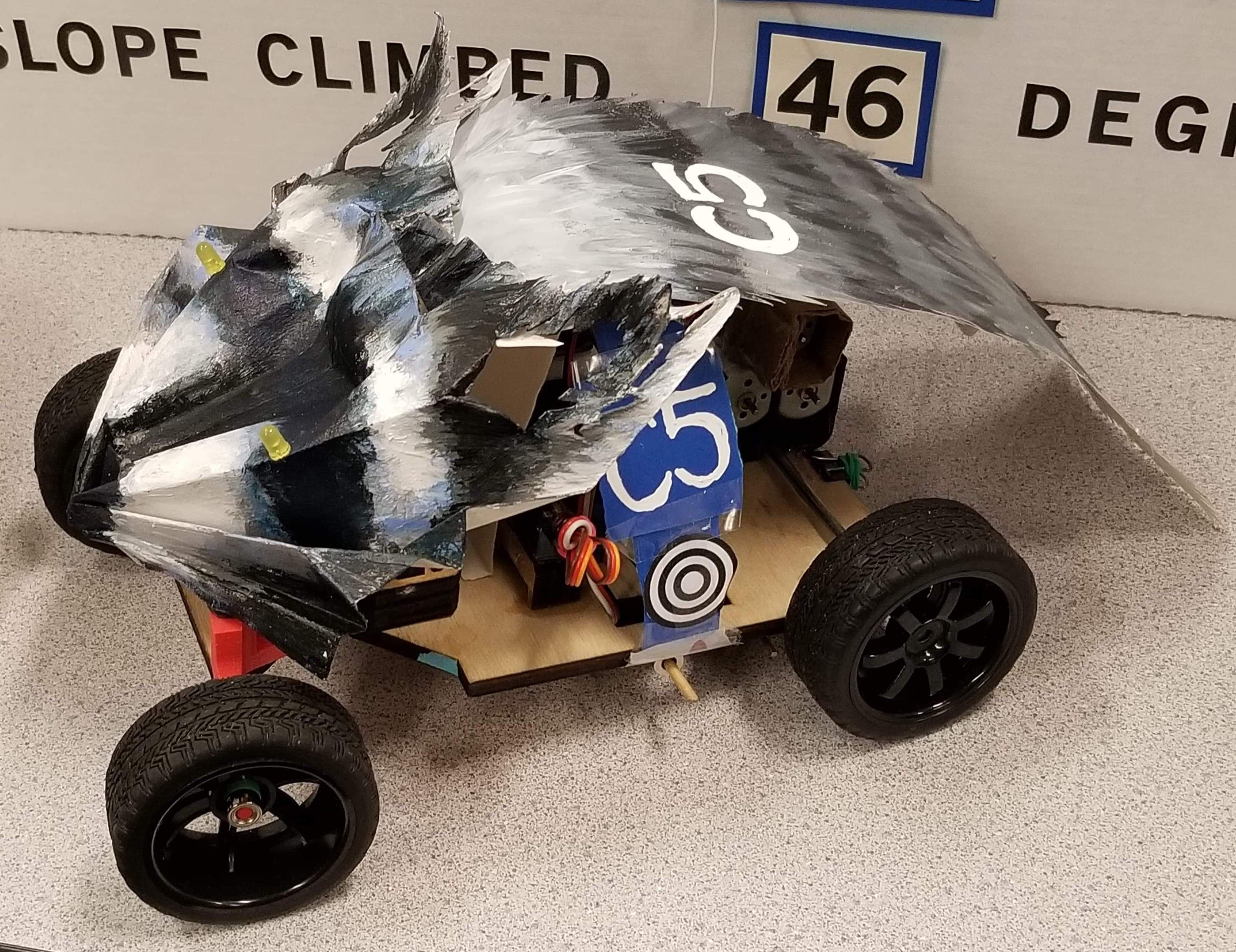
Final Rover with Aesthetics
Competition Round Video
We also wrote a report on the project and gave a presentation. I also did a review analysis on our design to improve our requirement and evaluation criteria generation stage, have a more robust risk analysis using Failure Modes and Effects Analysis, and redesigned some components for Design for Manufacturing and Assembly, and Design for Usability. Some of the DFMA examples are seen below.
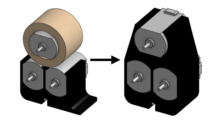
I redesigned the motor mount to hold all three motors instead of having it be two pieces
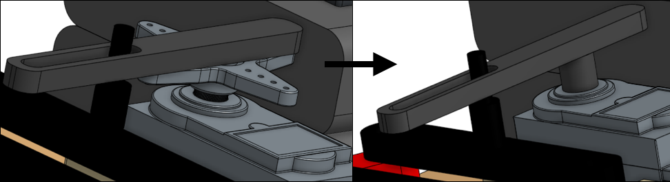
I redesigned the servo arm to be one streamlined piece instead of the two pieces that would need to be attached during assembly.